Networking Devices and Network Components

Networking devices are products used to connect networks. As computer networks grow in size and complexity, so do the networking devices used to connect them.

However, all networking devices share one or more common purposes.

  1. They allow a greater number of nodes to be connected to the network. A node is an endpoint of a network connection or a junction common to two or more lines in a network. Nodes can be processors, controllers, or workstations. Nodes vary in routing and other functional capabilities; they can be interconnected by links, and they serve as control points in the networks. Node is sometimes used generically to refer to any entity that can access a network and is frequently used interchangeably with device.
  2. They increase the distance over which a network can extend.
  3. They localize traffic on the network.
  4. They can merge existing networks.
  5. They isolate network problems so that the problems can be diagnosed more easily.

The following networking devices broadly used in network.

TCP/IP utilities | PING, TRACERT, ARP, Netstat, NBTSTAT/NetBIOS, IPCONFIG, NSLookup, WINIPCFG

Virtually every operating system with networking capabilities includes support for the TCP/IP protocols, and in most cases, the TCP/IP stack includes an assortment of utilities that enable you to gather information about the various protocols and about the network. Traditionally, these utilities run from the command line, although graphical versions are sometimes supplied. In many cases, a program uses the same syntax, even on different operating systems. This lesson examines some of the most common TCP/IP utilities and the purposes for which they are used.

Network Service | WINIPCFG

You can use the WINIPCFG utility to check a workstation's configuration details. For example, you can use the WINIPCFG utility to view the following information:

  • Current host hardware address
  • IP address
  • IP address lease and renewal times (for DHCP-assigned address)
  • Default gateway configuration

If your network is experiencing DHCP address problem, you can use the WINIPCFG utility's Renew/Renew All feature to force a workstation to attempt to renew an assigned address. When you this feature, however, the workstation release its IP address and cannot continue any IP-based operation.

Network Support | NSLookup

The nslookup application can be used to interactively query servers running a domain name service (DNS) application. It will send domain name query packets to any designated DNS server Three data elements are required in order to formulate a DNS query using nslookup:
A DNS server name/address
. The Internet style address that is being queried
. The type of record you are searching for

NSLOOKUP is used to query the Internet name server in order to obtain an address if you have a site name or a site name if you have an address. It can be very useful as a quick check to see if an electronic mail address is, in fact, reachable. To translate a name to an address,
type NSLOOKUP site name

You should get a report like this:

NSLOOKUP spiderhunter.com
Server: LOCALHOST
Address: 129.0.0.1

Name: spiderhunter.com
Address: 38.10.0.4


To translate an address to a name, type NSLOOKUP address and you should see something like this:
NSLOOKUP 128.171.90.10

Server: LOCALHOST
Address: 128.0.0.1
Name: uIc.edu
Address: 128.171.90.10

Network Support | IPCONFIG

When you run ipconfig at the Windows command line you see a display like this:


ipconfig Command

ipconfig [/? | /all | /release [adapter] | /renew [adapter]]


  • /?  -- Display help message.
  • /all  -- Display full configuration information.
  • /release  -- Release the IP address for the specified adapter.
  • /renew  -- Renew the IP address for the specified adapter.


The default is to display only the IP address, subnet mask and default gateway for each adapter bound to TCP/IP.

For Release and Renew, if no adapter name is specified, then the IP address leases for all adapters bound to TCP/IP will be released or renewed.

Network Support | NBTSTAT / NetBIOS

Nbtstat.exe is a command-line program that displays information about the NetBIOS over TCP/IP connections that Windows uses when communicating with other computers on the TCP/IP LAN.


The syntax for Nbtstat.exe is as follows:

NBTSTAT [-a name] [-A ipaddress] [-c] [-n] [-r] [-RI [-s] [-S] [-RR]

  • -a: name Displays the NetBIOS names registered on the computer identified by the name variable.
  • -A ipaddress: Displays the NetB1OS names registered on the computer identified by the ipaddress variable.
  • -c: Displays the contents of the local computer’s NetBIOS name cache.
  • -n: Displays the NetBIOS names registered on the local computer.
  • -r: Displays the number of NetBIOS names registered and resolved by the local computer, using both broadcasts and WINS.
  • -R: Purges the local computer’s NetBIOS name cache of all entries and reloads the LMHOSTS file.
  • -s: Displays a list of the computer’s currently active NetBIOS settings (identifying remote computers by name), their current status, and the amount of data transmitted to and received from each system.
  • -R R: Sends Name Release requests to WINS, then starts Refresh.

Network Support | Netstat (Network Statistics)

Netstat is a command-line program that displays information about a computer’s current network connections and about the traffic generated by the various TCP/IP protocols.
On UNIX computers, the program is simply called netstat, and on Windows computers, it is called Netstat.exe. The command-line parameters differ for the various implementations of Netstat, but the information they display is roughly the same.


The syntax for the Windows version of Netstat.exe is as follows:

NETSTAT [interval] [-a] [-p protocol] [-n] [-e] [-r] [-s]

interval: Refreshes the display every interval seconds until the user aborts the command.

  • -a: Displays the current network connections and the ports that are currently listening for incoming network connections.
  • -p: protocol Displays the currently active connections for the protocol specified by the protocol variable.
  • -n: When combined with other parameters, causes the program to identify computers using IP addresses instead of names.
  • -e: Displays incoming and outgoing traffic statistics for the network interface, broken down into bytes, unicast packets, non-unicast packets, discards, errors, and unknown protocols.
  • -r: Displays the routing table, plus the current active connections.
  • -s: Displays detailed network traffic statistics for the IP, ICMP, TCP and UDP protocols.


Network Support | Address Resolution Protocol (ARP)

The Address Resolution Protocol (ARP) enables a computer to convert IP addresses to the hardware addresses that the data-link layer protocol need to transmit frames. IP uses ARP to discover the hardware addresses to which each  of its datagrams will be transmitted. To minimize the amount of network traffic ARP generates, the computer stores the resolved hardware addresses in a cache in system memory. The information remains in the cache for a short period (usually 2 to 10 minutes), in case the computer has additional packets to send to the same address.

Windows systems include a command-line utility called Arp.exe that you can use to manipulate the contents of the ARP cache. 
For example, you can use Arp.exe to add to the cache the hardware addresses of computers you contact frequently, thus saving a little time and network traffic during the connection process. Addresses that you add to the cache manually are static, meaning that they are not deleted after the usual expiration period. The cache is stored in memory only, however, so it is erased when you reboot the computer. If you want to pre-load the cache whenever you boot your system, you can create a batch file containing Arp.exe commands and execute it from the Windows Startup group.

Arp.exe uses the following syntax:

ARP [-a {ipaddress}] [-n ipaddress] [-s ipaddress hwaddress {interface} [-d ipaddress {interface}]

  • -a {ipaddress} This parameter displays the contents of the ARP cache. The optional ipaddress variable specifies the address of a particular cache entry to displayed.
  • -n ipaddress This parameter displays the contents of the ARP cache, where ipaddress identifies the network interface whose cache you want to display.
  • -s ipaddress hwaddress {interface} This parameter adds a new entry to the ARP cache, where the ipaddress variable contains the IP address of the computer, the hwaddress variable contains the hardware address of the same computer, and the interface variable contains the IP address of the network interface in the local system whose cache you want yo modify.
  • -d ipaddress {interface} This parameter deletes the entry in the ARP cache that is associated with the computer represented by the ipaddress variable. The optional interface variable specifies the cache from which the entry should be deleted.

Network Support | TRACERT

You can use the TRACERT utility to determine the route that a packet may take to get from one device to another (if a route exists). You can also use this utility to determine the time that it takes the packet to reach routers and to identify Sluggish spots on the route.

The TRACERT utility uses interesting technology. If you analyze packets sent by the TRACERT utility, you will find that it uses the TTL counter to locate the route to another device.


When you run the TRACERT utility, it instructs the workstation to send a packet with a TTL count of 1 to the destination device. when this packet reach the local router, it discards the packet because the router cannot decrement the  TTL count to 0 and forward the packet. The router then sends an ICMP destination unreachable packet to the workstation.

This reply packet gives the workstation the IP address of the first router in the route. The workstation then send the same packet with a TTL of 2. The local router decrements the TTL count to 1 and forwards the packet.

The next router cannot decrement TTL count to 0 and forward the packet; so this router then sends an ICMP destination unreachable packet back to the workstation. This reply packet provides the IP address of the second router in the route.

The workstation continues incrementing the TTL count on each successive transmission until the workstation receives a reply back from the destination device.

you use the following syntax to launch  TRACERT utility:

TRACERT [-d] [-h maximum_hops] [-j host-list] [-w timeout] target_name

The parameter explain below:


  • -d: Use this parameter if you do not want to resolve addresses to host names.
  • -h: maximum_hops Use this parameter to determine the maximum number of hops to search for.
  • -j: host-list Use this parameter to test loose source route along host list. This test specifies certain devices a packet must cross to reach a destination. this test does not specify the exact route, which can include other devices.
  • -w: timeout Use this parameter to determine timeout milliseconds. Timeout determines how long the device waits for each reply. 

Network Support | PING Command

You can use the PING utility to query another IP device on the network to determine if the IP device is “alive” and how long it takes a packet to reach the device. This utility is one of the first tools you should use if the problem appears to be caused by a lack of connectivity between IP devices. The PING utility uses Internet Control Message Protocol (ICMP) echo packets to perform tests on the network.


You use the following syntax to launch the PING utility:

PING [-t] [-a] [-n count] [-l size] [-f] [-i TTL] [-v TOS] [-r count] [-s count] [[-j host-list] | [-k host-list]] [-w timeout] destination-list

The parameters are explained below:

  • -t: Use this parameter to ping the host continuously. To stop this test, press <Ctrl>C.
  • -a: Use this parameter to resolve addresses to host names.
  • -n: count Use this parameter to determine the number of echo requests to send.
  • -l: size Use this parameter to determine the ping packet size.
  • -f: Use this parameter to set the Don’t Fragment flag on the packet. This flag ensures that the packet is sent to the destination device in its entirety. If you set this flag, routers will be unable to fragment the packet to cross media that support smaller packet sizes. If a route includes such media, a router discards the packet and sends an ICMP destination unreachable packet to the sender.
  • -i: TTL Use this parameter to set the Time To Live (TTL) flag, which indicates the number of routers (hops) that a packet may cross. To limit the distance an ICMP echo packet can travel, you should define a small TTL value.
  • -v: TOS Use this parameter to set the Type Of Service (TOS) flag. If the network has been configured to support, you can force the PING utility to use a specific type of service for the connectivity test.
  • -r: count Use this parameter to record the number of hops to the destination IP device.
  • -s: count Use this parameter to timestamp the hops.
  • -j: host-list Use this parameter to test loose source route along host list. This test specifies certain devices a packet must cross to reach a destination. This test does not specify the exact route, which can include other devices.
  • -k: host-list Use this parameter to test strict source route along host-list. This test specifies all the devices a packet must cross to reach a destination. The packet cannot cross other devices.
  • -w: timeout Use this parameter to set the timeout in milliseconds. The timeout determines how long the IP device waits for a reply.


If a device is having problems communicating on the network, enter the following command at the DOS prompt: PING 127.0.0.1

The address 127.0.0.1 is the loopback address. If you enter this command, the device pings its own TCP/IP stack. if the device can’t see its own TCP/IP stack, the device can’t communicate on the network.
The Windows TCP/IP stack places an identifying pattern in each device’s ping packets. This identifying pattern, which is typically the alphabet, is located inside the ping packet padding area. You can use this identifying pattern to determine if a device is using the Windows TCP/IP stack.

You should not use the -t parameter unless you want to track and manually terminate the ping test. This parameter causes a continuous transmission of ping packets and may generate significant traffic on the network.

If you want to test the maximum packet size supported between two devices, use the -1 parameter (to define the maximum packet size) with the -f flag (to prevent the fragmentation of the packet). For example, if you wanted to know if you could send a 4 KB packet from a workstation to a NetWare 5 server in another building, you would enter the following command.

PING -f -l 4096 [destination]

You could then send the 4 KB packet to the server and find out if and where the packet would need to be fragmented.

Network Services

BOOTP:
BOOTP (Bootstrap Protocol) is an Internet protocol that enables a diskless workstation to discover its own IP address, the IP address of a BOOTP server on the network, and a file to be loaded into memory to boot the machine. This enables the workstation to boot without requiring a hard or floppy disk drive.

DHCP:
The Dynamic Host Configuration Protocols (DHCP) provides Internet hosts with configuration parameters. DHCP is an extension of BOOTP and consists of two components: a protocol for delivering host-specific  configuration parameters from a DHCP server to a host and a mechanism for allocation of network addresses to hosts.

DNS:
The Domain Name Service (DNS) protocol searches for resources using a database distributed among different name servers.

NAT:
NAT (Network Address Translation) is an Internet standard that enables a local area network (LAN) to use one set of IP addresses for internal traffic and a second set of addresses for external traffic. A NAT box is located where the LAN meets the Internet makes all necessary IP address translations.
NAT serves three main purposes:

  • Serves as a type of firewall by hiding internal IP addresses.
  • Provides more internal IP addresses for a company. As these are only for internal use, there is no possibility of conflict with IP addresses used by other companies and organizations.
  • Permits a company to merge multiple ISDN connections into a single internet connection.


ICS:
ICS (Internet connection sharing) is a method used for connecting multiple computers in a LAN to the Internet through a single connection and a single IP nddress. ICS typically uses NAT technologies to achieve this and works with most connection technologies, Including DSL, cable, ISDN, dial-up and satellite. The device with the modem or broadband interface that establishes the connection to the Internet is called the ICS host, or gateway while the other devices that connect to the Internet via the network and the ICS host are called ICS clients. If an ICS host fails, then all of the ICS clients lose their Internet connections.

WINS:
WINS (Windows Internet Naming Service), a system, which determines the IP address associated with a particular network computer. This is called name resolution. WINS supports network client and server computers running Windows and can provide name resolution for other computers with special arrangements. Determining the IP address for a computer is a complex process when DHCP servers assign IP addresses dynamically. For example, it is possible for DHCP to assign a different IP address to a client each time the machine logs on to the network.
WINS uses a distributed database that is automatically updated with the names of computers currently available and the IP address assigned to each one. DNS s an alternative system for name resolution suitable for network computers with fixed IP addresses.

SNMP:
The Internet community developed SNMP (Simple Network Message Protocol) to allow diverse network objects to participate in global network management architecture. Network managing systems can poll network entitles implementing SNMP for information relevant to a particular network management implementation. Network management systems learn of problems by receiving traps or change notices from network devices implementing SNMP.
A node on a network serves as an entrance to another network. In enterprises, the gateway is the computer that routes the traffic from a workstation to the outside network that is serving the Web pages. In homes, the gateway is the ISP that connects the user to the Internet.

Network Topologies | Bus, Star, Ring, Mesh, Tree

The physical layout, which describes how a LAN is constructed, is called the topology.


Bus Topology:
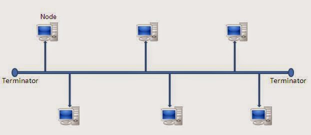
A bus topology is one in which all devices on the LAN are attached to a linear networking medium. This linear networking medium is often referred to as the trunk line, bus, or highway. Workstations and servers, is independently attached to the common bus wire through some kind of connection. The bus wire must end in a terminating resistance, or terminator, which absorbs electrical signals so they do not bounce, or reflect, back and forth on the bus.
       

Signal Transmission over a Bus Topology

The signal travels in both directions from the source when a source transmits data over the networking media in a bus topology. These signals are made available to all devices on the LAN. If the destination MAC address/destination IP address, carried by the data does not match that of a device, the device ignores the data. However, if the destination MAC address/destination IP address carried by the data does match that of a device, the device copies the data and passes it up to the data link and network layers of the OSI reference model.


Star Topology:
In LANs where the star topology is used, the networking media run from a central hub out to each device attached to the network. The physical layout of the star topology resembles spokes radiating from the hub of a wheel. As the figure shows, a central point of control is used in a star topology. When a star topology is used, communication between devices attached to the LAN is via point-to-point wiring to the central link or hub.


All network traffic in a star topology passes through the hub. Data is first sent to the hub. and then the hub directs data to the pathway of the device associated with the destination address carried by the data.
In a star topology. the hub can be either active or passive. If it is active, the hub not only connects the networking media, but it regenerates the signal and acts as a mutiport repeater. which is sometimes referred to as a concentrator. By regenerating the signal, such active hubs enable data to travel over greater distances. By contrast, a passive hub simply connects networking media.


Ring Topology:
A ring topology consists of a set of stations connected serially by cable. In other words, it Is a circle or ring of computers. There are no terminated ends to the cable; the signal travels around the circle.
In most instances data flow is in one direction only, with one single node receiving the transmission and relaying it to the next node in the ring. The ring topology is attractive because it is rarely subjected to the bottlenecks associated with hierarchical and star configurations. Moreover, the logic to implement a ring network is relatively simple.


Note that while this topology functions logically as ring, it is physically wired as a star. The central connector is not called a hub but a Multistation Access Unit or MAU.
Under the ring concept, a signal is transferred sequentially via a “token” from one station to the next. When a station wants to transmit, it grabs” the token, attaches data and an address to it, and then sends it around the ring. The token travels along the ring until it reaches the destination address. The receiving computer acknowledges receipt with a return message to the sender. The sender then releases the token for use by another computer.


Mesh Topology:
Mesh is a network topology in which devices are connected with many redundant interconnections between network nodes.
There is two types of mesh topologies: 1. Full Mesh and  2. Partial Mesh

Full mesh topology occurs when every node has circuit other node in a network. Full mesh is very expensive to implement but yields the greatest amount of redundancy, so in the event that on of those nodes fails, network traffic can be directed to any of the other nodes. Full mesh is usually reserved for backbone networks.


Partial mesh topology is less expensive to implement and yields less redundancy than full mesh topology. With partial mesh, some nodes are organized in a full mesh scheme but others are only connected to one or two in the network. Partial mesh topology is commonly found in peripheral networks connected to a full meshed backbone.


Tree Topology:
A tree topology combines characteristics of linear bus and star topologies. It consists of groups of star-configured workstations connected to a linear bus backbone cable. Tree topologies allow for the expansion of an existing network, and enable schools to configure a network to meet their needs.

Networking Device | Network Interface Adapters (NIC)

A network interface card is used to connect a computer to an Ethernet network. The card provides an interface to the media.

The network interface adapter (called network interface card, or NIC, installed in a computer's expansion slot) is the component that provides the link between a computer and the network of which it is a part. This may either by using an external transceiver or through an internal integrated transceiver mounted on the network interface card PCB. The card usually also contains the protocol control firmware and  Ethernet Controller needed to support the Medium Access Control (MAC) data link protocol used by Ethernet. Every computer must have an adapter that connects to the system’s expansion bus and provides a connection to the network medium.


Functions of Network Interface Adapter:
Network interface adapters perform a variety of functions that are crucial to getting data to and from the computer over the network. These functions are as follows:

  • Data encapsulation
  • Signal encoding and decoding
  • Data transmission and reception
  • Data buffering
  • Serial/parallel conversion
  • Media access control

Networking Device | Modems

Modem is any type of data communications equipment (DCE) that enables digital data transmission over the analog Public Switched Telephone Network (PSTN). The term “modem” (which actually stands for “modulator/demodulator") is usually reserved for analog modems, which interface, through a serial transmission connection such as the RS-232 interface, with data terminal equipment (DTE) such as computers. The modem converts the digital sign coming from the computer into an analog signal that can be carried Over a Plain Old Telephone Service (POTS) line. The term “digital modem” is sometimes used for ISDN terminal adapters, but this is something of a misnomer because no signal modulation actually takes place.


Modems generally have two interfaces:

  • An RS232 serial transmission interface for Connecting to the DTE, usually the computer
  • An RJ-11 telephone interface for connecting to the 4-wire PSTN telephone outlet in the local loop connection
  • The USB Modem is a compact external modem that interfaces with computer via a USB port. The modem is ideal for Apple users who own a computer without an internal modem and use a dial-up connection to connect to the internet. The modem can connect at speeds of up to 56 kbps using the V.92 protocol. Its compact form factor makes it ideal for notebook computer Users who find themselves on the road and need to dial-in to an office network or for home users who simply need to add an unobtrusive modem to their computer.


Modem types include the following:

  • Internal modems, which are Installed as interface cards inside the computer and might use some of the machine’s CPU processing power for functions such as encoding and data compression.
  • External modems, which are generally more expensive and connect to the serial port on the computer using a DB9 or DB25 connector. External modems are useful when several users need to share a modem.
  • PCMCIA modems, which are credit-cards-sized modems for laptop computers used by mobile workers.
  • Voice/data/fax modems, which can be used for file transfer, sending voice mail using associated software.

Networking Device | Gateways

Gateway is a broad category of network component that allow communication between different networking architectures and different protocols. Gateways generally operate at the higher levels of the Open Systems Interconnection (OSI) reference model for networking. They are commonly  connectivity between two different protocol stacks that might different systems. Examples include the following:

  • E-mail gateways for example, a gateway that receives Simple Mail Transfer Protocol (SMTP) e-mail, translates it into a standard X.400 format, and forwards it to its destination.
  • Gateway Service for NetWare acts as a gateway between the Common Internet File System (CIFS) protocol used on Windows networks and the NetWare Core Protocol (NCP) used on NetWare networks. CIFS, formerly known as SMB, is the native file-sharing protocol in Microsoft Windows 2000. When this gateway is enabled, Windows network clients can access NetWare services through the Gateway Service for NetWare gateway located on the Windows 2000 Server.
  • Gateways between a Systems Network Architecture (SNA) host and computers on a TCP/IP network, such as the one provided by Microsoft SNA Server.
  • A packet assembler/disassembler (PAD) that provides connectivity between a local area network (LAN) and an X.25 packet-switching network.

A gateway is usually a dedicated device or a set of services running on a dedicated computer. Gateways are essentially devices that direct network traffic in some fashion and translate that information.

Networking Device | Routers

Routers are another type of inter-networking device. As you learned earlier, bridges are primarily used to connect segments of a network. Routers are used to connect separate networks and to access the internet.


Routers provide end-to-end routing by passing data packets and routing traffic between different networks based on network protocol or Layer 3 information. Routers have the ability to make decisions about the best path for delivery of data on the network (like your mobile phone GPS system which help you find the efficient path). The problem of excessive broadcast traffic can be solved by using a router because routers do not forward broadcast frames unless specifically told to do so.


Difference Between Routers and Switches:
Routers differ from bridges in several respects. First, bridging occurs at Layer 2, the data link layer, whereas routing occurs at Layer 3, the network layer of the OSI reference model. Second, bridges use physical or MAC addresses to make data forwarding decisions. Routers use a different addressing scheme that occurs at Layer 3 to make forwarding decisions. They use network-layer addresses, which are referred to as Internet Protocol (IP), or logical addresses, rather than MAC addresses. Because IP addresses are implemented in software and refer to the network a device is located on, sometimes these Layer 3 addresses are referred to as protocol addresses or network addresses. Physical, or MAC, addresses are usually assigned by the NIC manufacturer and are hard-coded into the NIC. IP addresses, on the other hand, are usually assigned by the network administrator.

For routing to be successful, each network must have a unique network number, this unique network number is incorporated into the IP address assigned to each device attached to the network.


Networking Device | Switches

Switches operate in data-link (Layer-2) layer,which has largely replaced the bridge in the modern network, and which replacing routers in many instances as well. A switch is a box with multiple cable jacks in it that looks a lot like a hub. In fact, some manufacturers have hubs and switches of various sizes that are identical in appearance, except for their markings. The difference between a hub and a switch is that while a hub forwards every incoming packet out through all of its ports, a switch forwards each incoming packet only to the port that provides access to the destination system.

Switches essentially convert the LAN from a shared network medium to a dedicated one If you have a small network that uses a switch instead of a hub, each packet takes a dedicated path from the source computer to the destination, forming a separate collision domain for those two computers. Switches still forward broadcast messages to all of their ports, but not unicasts and multicasts. No systems receive packets destined for other systems, and no collisions occur during unicast transmissions because every pair of computers on the network has what amounts to a dedicated cable segment connecting them. Thus, while a bridge reduces unnecessary traffic congestion on the network, a switch all but eliminates it.

Another advantage of switching is that each pair of computers has the full bandwidth of the network dedicated to it. A standard Ethernet LAN using a hub might have 20 or more computers sharing the same I 0 Mbps of bandwidth. Replace the hub with a switch, and every pair of computers has its own dedicated 10 Mbps channel. This can greatly improve the overall performance of the network without the need for any workstation modifications at all. In addition, some switches provide ports that operate in Full-duplex mode, which means that two computers can send traffic in both directions at the same time using separate wire pairs within the cable. Full-duplex operation can effectively double the throughput of a 10 Mbps network to 20 Mbps.

Networking Device | Bridges

Bridges operate at Layer 2, the data link layer, of the OSI reference model and are not required to examine upper-layer information. Therefore, a bridge eliminates unnecessary traffic and minimizes the chances of collisions occurring on a network by dividing it into segments and filtering traffic based on the station or MAC address.

Bridges filter network traffic by only looking at the MAC address. Therefore they can rapidly forward traffic representing any network-layer protocol. Because bridges only took at MAC addresses, they are not concerned with protocols. Consequently, bridges are only concerned with passing packets, or not passing packets based on their destination MAC addresses. The following are the important properties of bridges:


In other language,
Bridges do not promiscuously copy traffic to all ports, as hubs do, but learn which MAC addresses are reachable through specific ports. Once the bridge associates a port and an address, it will send traffic for that address only to that port. Bridges do send broadcasts to all ports except the one on which the broadcast was received.
Bridges learn the association of ports and addresses by examining the source address of frames that it sees on various ports. Once a frame arrives through a port, its source address is stored and the bridge assumes that MAC address is associated with that port. The first time that a previously unknown destination address is seen, the bridge will forward the frame to all ports other than the one on which the frame arrived.

  1. They are more intelligent than hubs-that is, they can analyze incoming packets and forward (or drop) them based on addressing information.
  2. They collect and pass packets between two network segments.
  3. They control broadcasts to the network.
  4. They maintain address tables.

Networking Device | Hubs

On a LAN, every workstation is connected to the network by means of some sort of transmission medium. Usually, each file server has only one NIC. Therefore, it would be impossible to connect every workstation directly to the file servers. To solve this problems, LANs may use hubs, which are common networking devices.

The term hub is used instead of repeater when referring to the device that serves as the center of a network.The following are the most important properties of hubs:
  1. They amplify signals.
  2. They propagate signals through the network.
  3. They do not require filtering.
  4. They do not require path determination or switching.
  5. They are used as network concentration points.


Hubs can also be understood to be hardware devices that contain multiple independent but connected modules of network equipment.In a LAN, where hubs act as multiport repeaters, they sometimes referred to as a concentrators. In such cases, hubs are used to split the networking media or provide for multiple connections.

The disadvantage of using a hub is that it cannot filter network traffic. Filtering generally refers to a process or device that screens network traffic for certain characteristics, such as source address, destination address, or protocol, and determines whether to forward or discard that traffic based on the established criteria. On a hub, data arriving at one port is sent out on all other ports. Consequently, a hub passes data to all other sections or segments of a network, regardless of whether the data needs to go there or not.

How it's work?
When data enters the hub through any of its ports, the hub amplifies the signal and transmits it out through all of the other ports. This enables a star network to have a shared medium, even though each computer has its own separate cable The hub relays every packet transmitted by any computer on the network to all of the other computers, and amplifies the signals. The maximum segment length for a UTP cable on an Ethernet network is 100 meters. A segment is defined as the distance between two communicating computers. However, because the hub also functions as a repeater, each of the cables connecting a computer to a hub port can be up to 100 meters long, allowing a segment length of up to 200 meters when one hub is inserted in the network.

Networking Device | Repeaters

Like networking media, repeaters are networking devices that exist at Layer 1, the physical layer, of the OSI reference model.


To begin understanding how a repeater works, it is important to first understand that as data leaves a source and goes out over the network, it is transformed into either electrical or light impulses that pass along the networking media. These impulses are referred to as signals. When signals first leave a transmitting station, they are clean and easily recognizable. However, the longer the cable length, the weaker and more deteriorated the signals become as they pass along the networking media.

For example, specifications for Category 5 twisted-pair Ethernet cable establish the maximum distance that signals can travel along a network as 100 meters. If a signal travels beyond that distance, there is no guarantee that a NIC will be able to read the signal. A repeater can provide a simple solution if this problem exists.


Using Repeaters to increase the Extent of the Network
Repeaters can increase the distance over which a network can extend so that signals will not become unrecognizable to devices receiving them on the network. Repeaters take in weakened signals, clean them up, amplify them and send them on their way along the network, thereby increasing the distance over which a network can operate.


Using Repeaters to Increase the Number of Network Nodes
In networking a common problem is that there are too many devices connected to a network. Signals become weaker and more deteriorated when there are too many devices attached to a network because each device attached to e network causes the signal to degrade slightly. Moreover, because a signal has to pass by too many stations or nodes, it can become so weak that it is unrecognizable to devices receiving it. However, a repeater can provide a simple solution if this problem exists as mentioned in the previous section.

http://www.basicnetworking.org/

Copyright © Basic Networking | Terms and Conditions | Privacy Policy